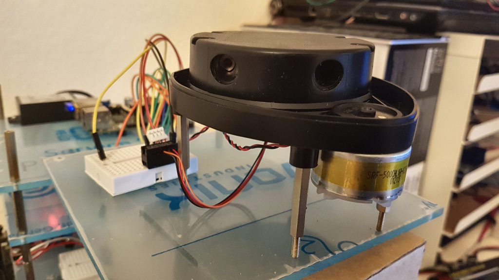
So today my Neat XV LIDAR module arrived, and I had to test it directly with the Raspberry Pi. For everyone that does not know this wonderful piece of hardware yet: It is a low-cost 360-degree spinning laserscanner that is usually scavenged from the Neato XV vacuum-robots. In Germany it is quite hard to get your hands on one, so I ordered one via ebay from the US.
Test-Setup:
According to https://xv11hacking.wikispaces.com/LIDAR+Sensor, the wires of the LIDAR-unit have the following pinout:
Red: 5V
Brown: LDS_RX
Orange: LDS_TX
Black: GND
Although the logic-unit is supplied with 5V, the interface (rx/tx) is 3.3v. Perfect for talking to a raspberry pi!
As stated in the wiki, the sensor (without the motor!) draws ~45mA in idle and ~135mA when in use (rotating).
For these first tests, I wired it up by connection the power-lines of the logic to an external 5v power supply (that can definitely provide the needed mA), the TX of the scanner directly to the RX of the raspberry pi, connected the GNDs. Without connecting the motor yet and just powering the logic-unit on while connected to the serial (115200 baud, 8N1), it would greet me with the following welcome-message:
Piccolo Laser Distance Scanner
Copyright (c) 2009-2011 Neato Robotics, Inc.
All Rights Reserved

Loader	V2.5.15295
CPU	F2802x/c001
Serial	KSH14415AA-0358429
LastCal	[5371726C]
Runtime	V2.6.15295
#Spin...3 ESCs or BREAK to abort
After that I hooked up the motor to an external power-supply with approx. 3V.
Meanwhile, the final connection as it is installed in the robot is the one shown below. I use a the ULN2803A Darlington Transistor Array to drive the motor, as it draws 60mA and above (the single pins of the RPi are specified with a maximum of 50mA, so we use this chip to handle the current). The red wire of the motor is connected directly to the 5V-rail of the Raspberry Pi, the black wire is connected to Out-7 of the ULN2803A with a Resistor of 15 Ohm to bring down the voltage from 5V to approximately 3V. In-7 is currently just connected to +5V, but could be wired to the raspberry pi in order to turn the motor on or off, or control it using PWM. The logic-VCC and -GND are directly connected to the Raspberry Pi’s 5V rail, the TX-line of the Laser Distance Sensor is connected to RX on the Raspberry Pi.
After spinning it up to 300rpm and got my first measurement-packets, which sadly did not look very promising:
fa:a6:f0:4a:55:80:00:00:55:80:00:00:55:80:00:00:55:80:00:00:4e:20:
fa:a7:e9:4a:55:80:00:00:55:80:00:00:55:80:00:00:55:80:00:00:52:19:
fa:a8:e9:4a:55:80:00:00:55:80:00:00:55:80:00:00:55:80:00:00:56:19:
fa:a9:e9:4a:55:80:00:00:55:80:00:00:55:80:00:00:55:80:00:00:5a:19:
fa:aa:e9:4a:55:80:00:00:55:80:00:00:55:80:00:00:55:80:00:00:5e:19:
fa:ab:e9:4a:55:80:00:00:55:80:00:00:55:80:00:00:55:80:00:00:62:19:
fa:ac:e9:4a:55:80:00:00:55:80:00:00:55:80:00:00:55:80:00:00:66:19:
fa:ad:e2:4a:55:80:00:00:55:80:00:00:55:80:00:00:55:80:00:00:6a:12:
fa:ae:e2:4a:55:80:00:00:55:80:00:00:55:80:00:00:55:80:00:00:6e:12:
fa:af:e2:4a:55:80:00:00:55:80:00:00:55:80:00:00:55:80:00:00:72:12:
fa:b0:e2:4a:55:80:00:00:55:80:00:00:55:80:00:00:55:80:00:00:76:12:
fa:b1:e2:4a:55:80:00:00:55:80:00:00:55:80:00:00:55:80:00:00:7a:12:
fa:b2:e2:4a:55:80:00:00:55:80:00:00:55:80:00:00:55:80:00:00:7e:12:
The packet-format (https://xv11hacking.wikispaces.com/LIDAR+Sensor) is the following:
22 Bytes: <start> <index> <speed_L> <speed_H> [Data 0] [Data 1] [Data 2] [Data 3] <checksum_L> <checksum_H>
where:
- start is always 0xFA
- index is the index byte in the 90 packets, going from 0xA0 (packet 0, readings 0 to 3) to 0xF9 (packet 89, readings 356 to 359).
- speed is a two-byte information, little-endian. It represents the speed, in 64th of RPM (aka value in RPM represented in fixed point, with 6 bits used for the decimal part).
- [Data 0] to [Data 3] are the 4 readings. Each one is 4 bytes long, and organized as follows :
`byte 0 : <distance 7:0>`
`byte 1 : <„invalid data“ flag> <„strength warning“ flag> <distance 13:8>`
`byte 2 : <signal strength 7:0>`
`byte 3 : <signal strength 15:8>`
I wrote up a little python script to decode the packets in real-time for me:
#!/usr/bin/python
import serial
import time
import math

# Some settings and variables
outfile = open("outfile.txt", "w+")
print("Start")

f = serial.Serial(port='/dev/ttyAMA0',
                            baudrate=115200,
                            parity=serial.PARITY_NONE,
                            stopbits=serial.STOPBITS_ONE,
                            bytesize=serial.EIGHTBITS,
                            timeout=0)

def decode_string(string):
    print string
    data = []

    for byte in string.strip("\n").split(":")[:21]:
        data.append(int(byte,16))

    start = data[0]
    idx = data[1] - 0xa0
    speed = float(data[2] | (data[3] << 8)) / 64.0
    in_checksum = data[-2] + (data[-1] << 8)

    # first data package (4 bytes after header)
    angle = idx*4 + 0
    angle_rad = angle * math.pi / 180.
    dist_mm = data[4] | ((data[5] & 0x1f) << 8)
    quality = data[6] | (data[7] << 8)

    if data[5] & 0x80:
         print "X - ",
    else:
        print "O - ",
    if data[5] & 0x40:
         print "NOT GOOD"
    print "Speed: ", speed, ", angle: ", angle, ", dist: ",dist_mm, ", quality: ", quality
    #print "Checksum: ", checksum(data), ", from packet: ", in_checksum
    outfile.write(string+"\n")
    print "-----------"

byte = f.read(1)
started = False
string = "Start"
while True:
    if byte != '':
        enc = (byte.encode('hex') + ":")
        if enc == "fa:":
            if started:
                try:
                    decode_string(string)
                except Exception, e:
                    print e

            started = True
            string = "fa:"
        elif started:
            string += enc
        else:
            print "Waiting for start"

    byte = f.read(1)
outfile.close()
print("End")
Until now I did not have any luck. One thing I noticed was that during the spin-up of the motor to full speed, it would give me valid readings for approximately half a second (without the bad-flag). However, even if I adjusted the rpm to exactly these values, it would still output only bad packets. Additionaly, the rotational speed at which those few good packets came through always changed, so my current guess is that either the laser- oder imager-unit is faulty, or that their connection through the slip-ring is somehow bad.
I contacted the seller and he agreed to send another unit, so lets wait. Yay, the new unit arrived, and it is working!
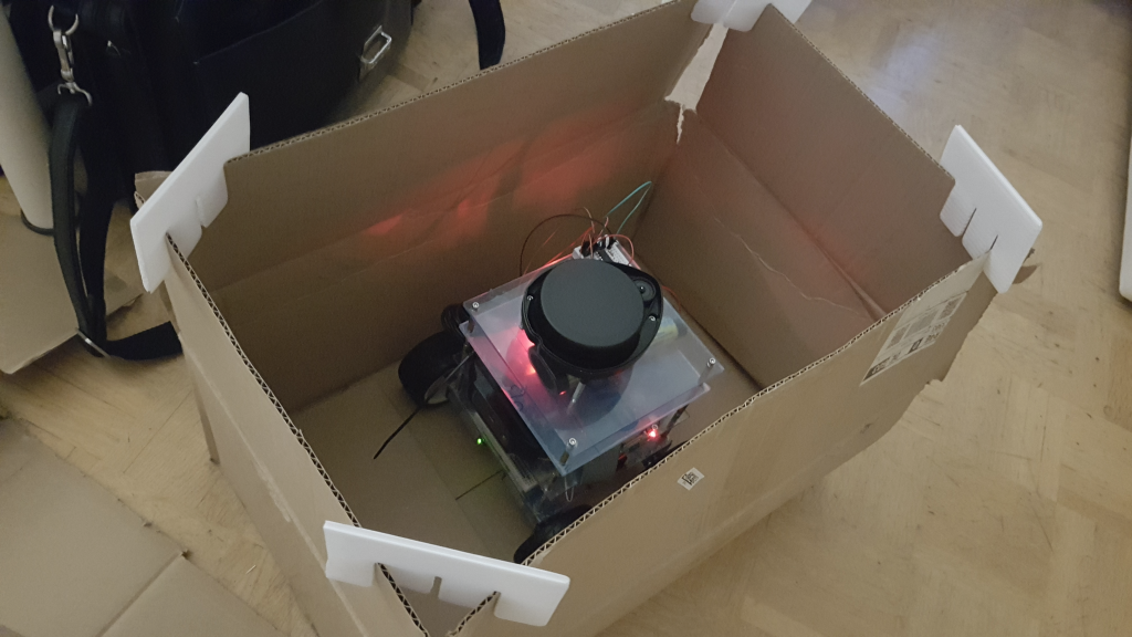
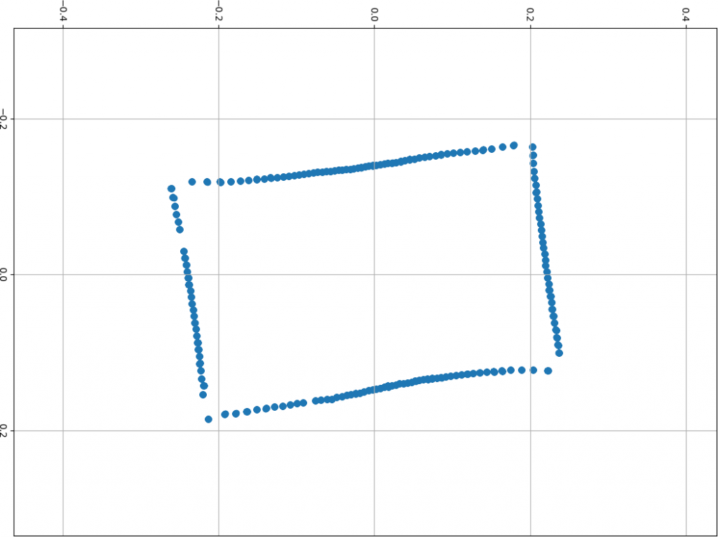
Below is my test-setup with the robot in a cardboard-box, and the visualization of the values I read from the Picollo (leave a comment if you want the script) using Numpy and Matplotlib:


Comments (13)