After I completed the circuitry to power my raspberry pi from a battery pack, I wanted a way to display the voltage of the battery pack, and be able to access the voltage level from the raspberry pi, so it can shutdown automatically when critical voltage levels are reached to prevent damage to the filesystem or draining the battery too much.
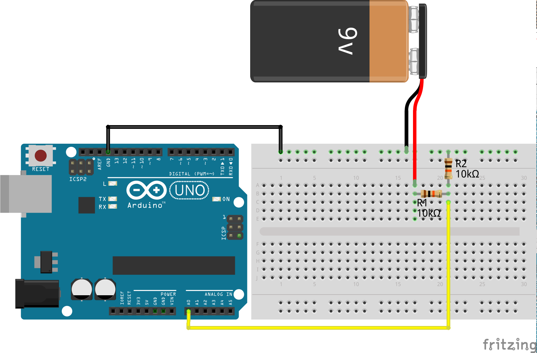
Our Pi can stand at most 5V per input pin, so how do we measure voltages like the 7.4V of our battery and above (if its full, it has more than 7.4V)? We have to scale the highest expected voltage down to 5V! The easiest way to do this is by using a voltage divider. Suppose the 9v-battery in the schematic below is our battery, and the arduino is powered over USB. We connect GND of both and divide the 9V of the battery by using a voltage divider. If both resistors in the schematic below are equal, we effectively halve the voltage. Remember the formula for voltage dividers (without load):

In our case, that means if the battery is full and has 9V:

So the maximal expected voltage at our analog-in is 4.5V!
By using the arduino-function analogRead(A0), we get a value between 0 and 1023, which represents the voltage scale from 0-5V. We know that whatever we read will be halve of the actual external voltage, so to convert this value back to the actual voltage:
int sensorValue = analogRead(A0);
voltage = sensorValue * (10.0 / 1023.0)
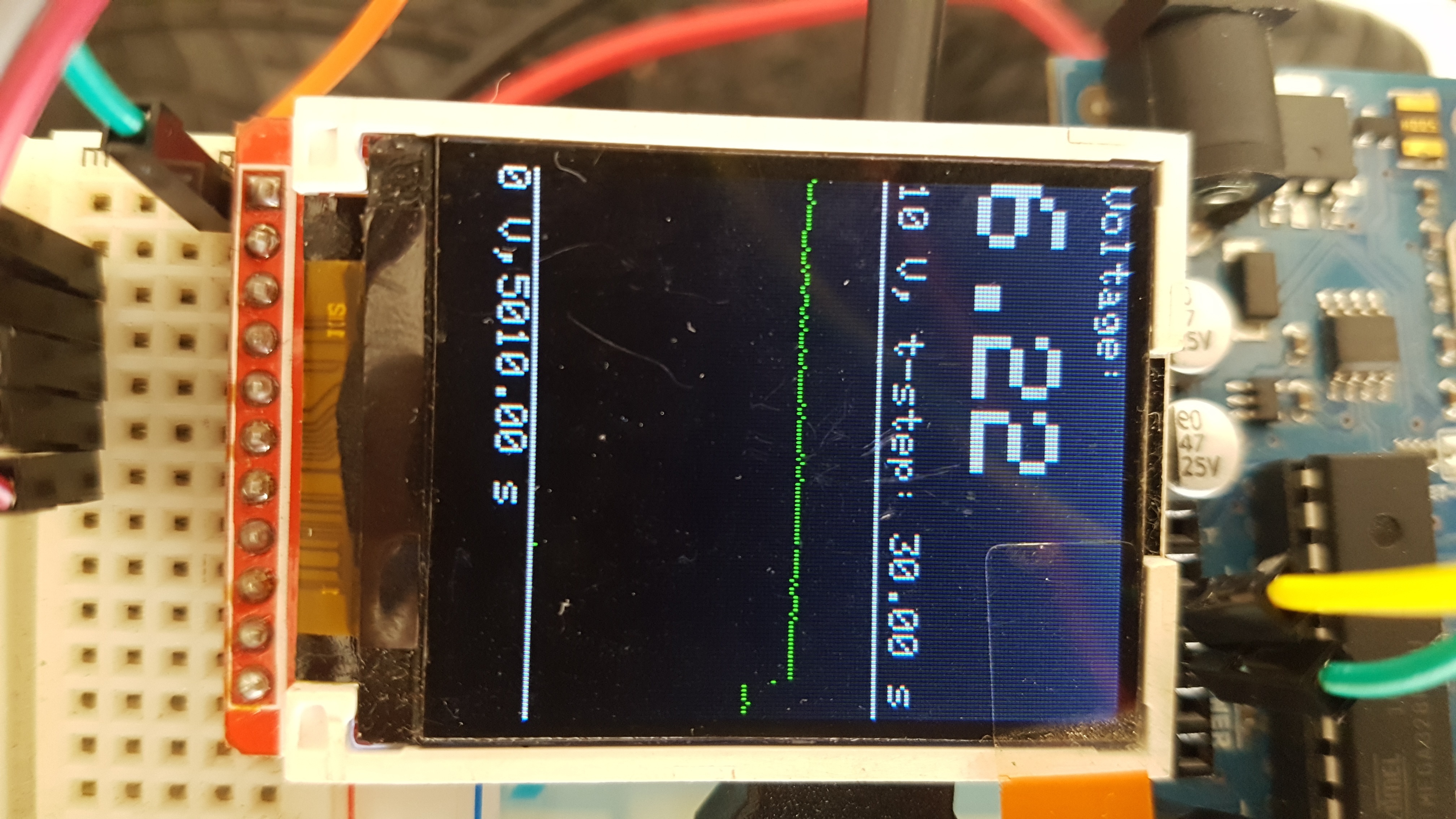
Now this can be put into a nice little script to output this value over serial to the Raspberry Pi, and display it somewhere. I chose to use a 1.44 Inch Spi Tft Lcd Color Screen St7735 with 128×160 pixels and wrote some code to save and display measurements at certain time-intervalls in a rolling fashion, which results in this:
The display can be wired as follows:
| Display (SainSmart) | Display Adafruit | Arduino | Meaning |
| SCL | SCK | 13 | Display Clock |
| SDA | MOSI | 11 | Display Data |
| RS/DC | D/C | 9 | Command/Data mode |
| RES | RESET | 8 | Reset |
| CS | TFT_CS | 10 | Chip select |
To run this script, you need to wire up your display and the voltage divider as shown above, and download and place the adafruit_gfx and adafruit_st7735 libraries into your arduino library folder.
#define sclk 13
#define mosi 11
#define cs   10
#define dc   9
#define rst  8  // y

#include <Adafruit_GFX.h>    // Core graphics library
#include <Adafruit_ST7735.h> // Hardware-specific library
#include <SPI.h>

Adafruit_ST7735 tft = Adafruit_ST7735(cs, dc, rst);

#if defined(__SAM3X8E__)
    #undef __FlashStringHelper::F(string_literal)
    #define F(string_literal) string_literal
#endif

float timestep = 30.f; // save a measuremnt for every timestep
unsigned long last_time = 0; // start time

int sensorPin = A0;
int count = 0; // to measure overall time and set array indices
int ofy = 140; // y-offset for values and scales
int scale=8; // scaling of pixels/volt
float values[128];

/*
void testdrawtext(String text, uint16_t color, uint16_t tsize) {
  tft.setCursor(0, 0);
  tft.setTextSize(tsize);
  tft.setTextColor(color, ST7735_BLACK); // second color is background, overwrite!
  tft.setTextWrap(true);
  tft.print(text);
}
*/

void setup(){
  tft.initR(INITR_REDTAB);
  tft.fillScreen(ST7735_BLACK);
  // creates the 0/10-lines and clears measurement area
  setup_measurements();

}

float getVoltage(){
  int sensorValue = analogRead(sensorPin);
  return sensorValue * (10.0 / 1023.);

}

void setup_measurements(){
  // create the bottom line and text
  tft.setCursor(0, ofy+3);
  tft.setTextSize(1);
  tft.print("0 V, ");
  tft.drawLine(0, ofy+1, tft.width()-1, ofy+1, ST7735_WHITE);

  // create top-line and text
  tft.setCursor(0, ofy-10*scale-1-10);
  tft.setTextSize(1);
  tft.print("10 V");
  tft.print(", t-step: ");
  tft.print(timestep);
  tft.print(" s");
  tft.drawLine(0, ofy-10*scale-1, tft.width()-1, ofy-10*scale-1, ST7735_WHITE);
}

void printVoltage(float volt, uint16_t color, uint16_t tsize){
  tft.setCursor(0, 0);
  tft.setTextSize(1);
  tft.setTextColor(color, ST7735_BLACK); // second color is background, overwrite!
  tft.setTextWrap(true);
  tft.println("Voltage: ");
  tft.println();

  tft.setTextSize(tsize);
  tft.println(volt);
}

void loop(){
  printVoltage(getVoltage(), ST7735_WHITE, 3);

  if (millis() - last_time >= timestep*1000){
    if (count >= tft.width()-1){
      // shift all array elements to the left, replace last value
      for(int k=0; k<127;k++){
        // paint all old pixels black instead of drawing complete lines
        tft.drawPixel(k, ofy-scale*values[k], ST7735_BLACK);
        values[k] = values[k+1];
        tft.drawPixel(k, ofy-scale*values[k], ST7735_GREEN);
      }
      values[127] = getVoltage();
    }else{
      values[count] = getVoltage();
      tft.drawPixel(count, ofy-scale*values[count], ST7735_GREEN);
    }
    count = count + 1;

    // draw elapsed time
    tft.setCursor(25, ofy+3);
    tft.setTextSize(1);
    tft.print(count*timestep);
    tft.print(" s");

    last_time = millis();
  }
}